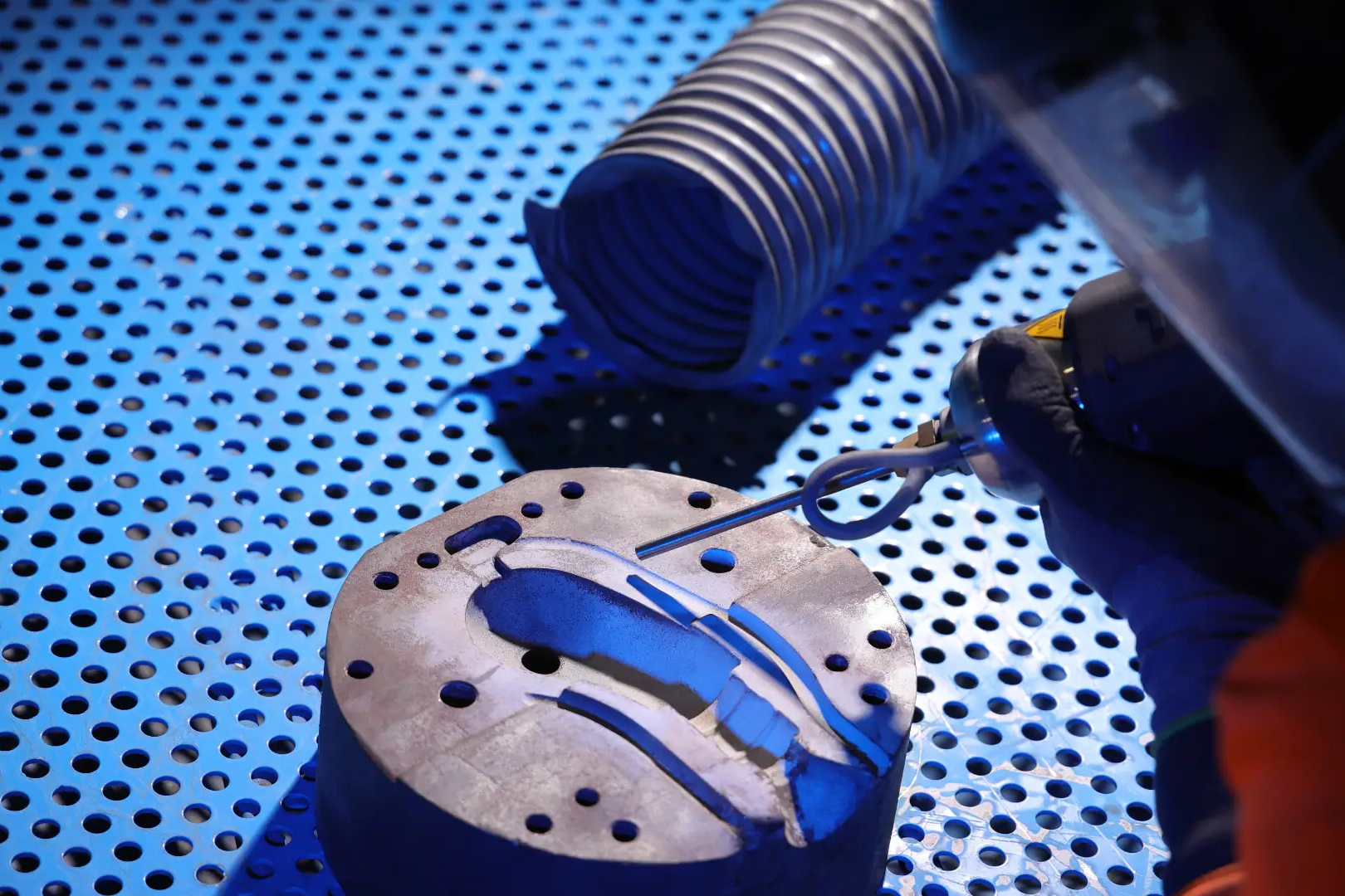
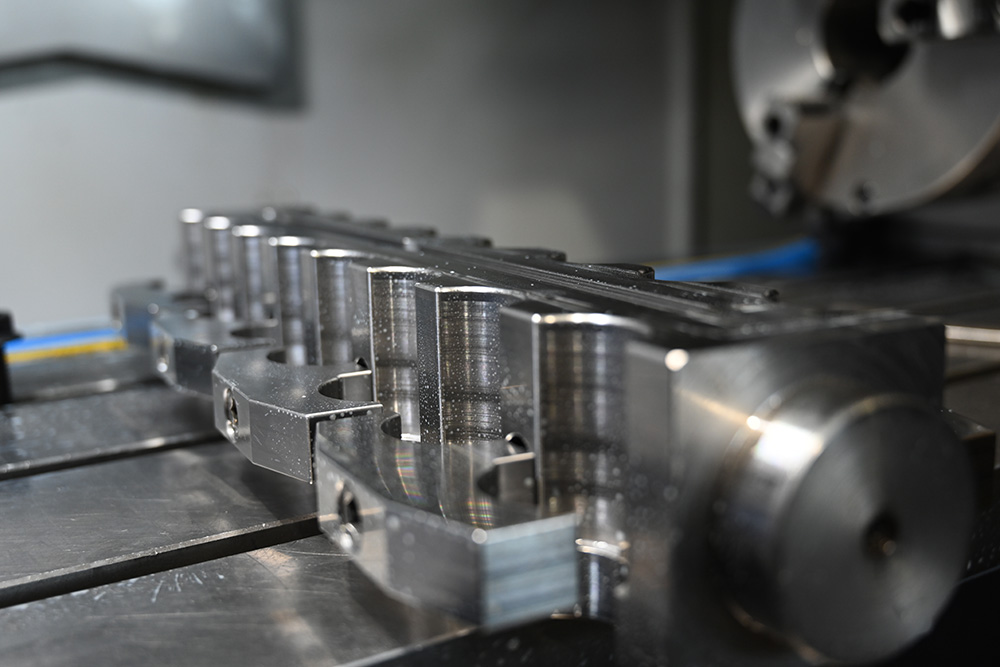
CNC machining tolerances are essential for achieving the desired precision and accuracy in manufactured parts. This comprehensive guide delves into the various aspects of CNC machining tolerances, providing detailed insights into their calculation, types, and importance. Understanding these CNC Machining Tolerances is crucial for producing high-quality components that meet specific requirements and industry standards.
What are Machining Tolerances?
CNC machining tolerances define the allowable variation in a physical dimension of a manufactured part. They set the limits within which a part’s dimensions can vary, ensuring that the part will fit and function correctly in its intended application. Tight tolerances are essential in industries such as aerospace, medical devices, and automotive manufacturing, where precision is paramount. – Factory.com
Calculation and Expression of Machining Tolerances
Machining tolerances are expressed as a range within which the dimensions of a part must fall. This range is determined based on the desired precision and the capabilities of the machining process. Tolerances can be expressed in various forms, including:
Geometric Dimensioning and Tolerancing (GD&T)
GD&T is a standardised system that uses symbols and annotations on engineering drawings to define and communicate engineering tolerances. It specifies the allowable variations in form, orientation, location, and size of part features, ensuring that parts fit together correctly and function as intended.
Why High-Precision/High-Quantity Machining?
High-precision machining is essential for applications where even slight deviations can cause significant issues. High-quantity machining ensures efficient and consistent production of parts, reducing the risk of errors and enhancing production speed.
Tolerancing Guidelines for CNC Machining
Basic Size
The basic size is the theoretical exact size from which limits of size are derived. It serves as a reference point for specifying CNC machining tolerances and is the nominal dimension around which the allowable variations are defined. For example, if the basic size of a shaft is 10 mm, the actual dimensions will be specified within a certain range around this nominal value, such as 10 mm ± 0.05 mm.
Actual Size
The actual size is the measured size of the finished part. It is the real dimension obtained after machining and must fall within the specified tolerance limits. Measuring the actual size accurately is crucial for ensuring that the part meets the required specifications and functions as intended. Deviations from the actual size can affect the part’s fit, performance, and reliability.
Limits
Limits define the maximum and minimum sizes that a part can be, as defined by the tolerance. These limits set the boundaries for the allowable variations in dimensions. For example, if a dimension is specified as 10 mm +0.1/-0.05 mm, the upper limit is 10.1 mm, and the lower limit is 9.95 mm. Staying within these limits ensures that the part meets the design requirements and performs correctly in its application.
Deviation
Deviation is the difference between the actual size and the basic size. It quantifies how much the actual dimension deviates from the nominal dimension. Deviation can be positive (when the actual size is larger than the basic size) or negative (when the actual size is smaller than the basic size). Understanding and controlling deviation is essential for maintaining the desired tolerances and ensuring part quality.
Datum
A datum is a reference point, line, or surface on a part used to establish dimensions. Datums provide a common reference for measuring and defining tolerances. They are critical in ensuring consistent and accurate measurements, especially in complex parts with multiple features. Using datums helps align and position parts correctly during assembly and inspection, improving overall precision.
Maximum Material and Least Material Requirements
Maximum Material Condition (MMC) and Least Material Condition (LMC) define the conditions of a part feature with the maximum and minimum material present, respectively. MMC is the condition where a feature contains the most material (e.g., the smallest hole size or the largest shaft size). LMC is the condition where a feature contains the least material (e.g., the largest hole size or the smallest shaft size). These concepts are crucial for ensuring proper fit and function, especially in mating parts.
Decimal Places
Maximum Material Condition (MMC) and Least Material Condition (LMC) define the conditions of a part feature with the maximum and minimum material present, respectively. MMC is the condition where a feature contains the most material (e.g., the smallest hole size or the largest shaft size). LMC is the condition where a feature contains the least material (e.g., the largest hole size or the smallest shaft size). These concepts are crucial for ensuring proper fit and function, especially in mating parts.
Calculating Tolerance
Tolerance is calculated by determining the permissible variation in dimensions, typically using the formula: Tolerance = Upper Limit – Lower Limit. For example, if the upper limit is 10.1 mm and the lower limit is 9.9 mm, the tolerance is 0.2 mm. Calculating tolerance accurately is essential for defining the acceptable range of variation and ensuring that the part meets the specified requirements.
Different Types of Machining Tolerances
Bilateral Tolerance
Bilateral tolerance allows variation in both directions (both above and below the specified dimension). This means that the dimension can vary by a certain amount in either direction from the nominal value. For example, if a dimension is specified as 10 mm ± 0.1 mm, the actual dimension can range from 9.9 mm to 10.1 mm. Bilateral tolerances are common because they provide flexibility in manufacturing while still maintaining control over the part’s dimensions.
Limit Tolerances
Limit tolerances define the maximum and minimum permissible sizes of a part. These tolerances specify the upper and lower bounds within which a dimension must lie. For example, a dimension with a limit tolerance of 10.0 mm +0.1/-0.2 mm can vary between 9.8 mm and 10.1 mm. Limit tolerances are useful for ensuring parts do not exceed critical size constraints, making them suitable for tight-fitting components.
Profile Tolerances
Profile tolerances control the form, orientation, and location of the surface profile. These tolerances specify the allowable variation in the shape of a part’s surface. For instance, a profile tolerance can define how much a curved surface can deviate from its ideal shape. Profile tolerances are crucial in applications where the surface contour affects the part’s function, such as aerodynamic surfaces in aerospace components.
Location Tolerance
Location tolerances control the location of features relative to each other. They ensure that features such as holes, slots, and bosses are positioned correctly on a part. Location tolerances are expressed as positional tolerances, specifying the allowable variation in the location of a feature. Accurate location tolerances are essential for assembly, where the relative positions of features determine how parts fit together.
Form Tolerances
Form tolerances control the shape of individual features. These tolerances ensure that features such as flat surfaces, cylindrical shapes, and straight edges conform to their intended geometries. Common form tolerances include flatness, straightness, circularity, and cylindricity. Maintaining precise form tolerances is critical in applications where the shape of a feature affects the part’s performance.
Runout Tolerance
Runout tolerance controls the wobble or deviation from the true rotational axis. It specifies the allowable variation in the roundness and alignment of rotating parts. Runout tolerances are essential for components such as shafts and bearings, where even minor deviations can cause vibration, noise, and wear. Ensuring tight runout tolerances helps maintain smooth and efficient operation of rotating machinery.
Unequally Disposed Tolerances
Unequally disposed tolerances allow different variations on each side of the nominal dimension. For example, a dimension might be specified as 10 mm +0.2/-0.1 mm, meaning it can vary from 9.9 mm to 10.2 mm. This type of tolerance provides flexibility in one direction while maintaining tighter control in the other direction. Unequally disposed tolerances are useful when one direction of variation has a greater impact on the part’s function than the other.
Geometric Dimensioning and Tolerancing (GD&T)
GD&T is a comprehensive system for defining tolerances on part features. It uses symbols and annotations to specify the allowable variations in form, orientation, location, and size. GD&T ensures that parts fit together correctly and function as intended, even when manufactured by different suppliers. It is widely used in industries that require high precision and consistency, such as aerospace and automotive manufacturing.
Geometric Dimensioning and Tolerancing (GD&T)
- Router: ± 0.005″ or 0.13 mm
- Lathe: ± 0.005″ or 0.13 mm
- Router (Gasket Cutting Tools): ± 0.030″ or 0.762 mm
- Milling (3-axis): ± 0.005″ or 0.13 mm
- Milling (5-axis): ± 0.005″ or 0.13 mm
- Engraving: ± 0.005″ or 0.13 mm
- Rail Cutting Tolerances: ± 0.030″ or 0.762 mm
- Screw Machining: 0.005″ or 0.13 mm
- Steel Rule Die Cutting: ± 0.015″ or 0.381 mm
- Surface Finish: 125RA
Important Things to Remember When Dealing With Tolerances
Do you need tight tolerances?
Tighter tolerances often require more advanced machining techniques and can increase costs. Assess whether the application’s requirements justify the need for tight tolerances.
Costs
Higher precision and tighter CNC machining tolerances typically come with increased costs due to the need for advanced machinery and longer production times.
Inspection
Precise measurement tools and techniques are required to ensure parts meet tolerance specifications. Regular inspection is crucial for maintaining quality.
Machining Methods
Different machining methods have varying capabilities for achieving tight CNC machining tolerances. Select the appropriate method based on the required precision.
Surface Roughness Considerations for CNC machining tolerances
Surface finish quality can impact the tolerance and functionality of the part. Consider surface roughness requirements when specifying tolerances.
How to Find the Right Tolerance?
ISO 2768 standards
These standards specify general tolerances for linear dimensions, angular dimensions, and geometrical tolerances, ensuring consistency and quality in manufacturing processes.
What is ISO 2768?
ISO 2768 provides guidelines for tolerances to ensure consistency and quality in manufacturing processes. It defines general tolerances for linear dimensions, angular dimensions, and geometrical tolerances.
Tips for Tighter CNC Machining Tolerances
- Use high-quality materials and tools. High-quality materials and precision tools help achieve tighter CNC machining tolerances and improve overall part quality.
- Implement precise measurement and inspection techniques. Regular inspection and precise measurement tools ensure parts meet specified tolerances.
- Maintain machinery and calibration regularly. Proper maintenance and calibration of machinery are essential for maintaining high precision.
- Work with experienced machinists and engineers. Skilled machinists and engineers can identify potential issues and optimise machining processes for tighter tolerances.
What is considered a tight tolerance in machining?
A tight tolerance in machining is typically within ±0.001 inches or ±0.025 mm, though the exact value depends on the specific application and industry requirements. Tighter tolerances require advanced machining techniques and more precise control.
Conclusion
Understanding and implementing proper CNC machining tolerances is essential for producing high-quality, reliable parts. By considering factors like material properties, dimensional requirements, and machining capabilities, manufacturers can achieve the desired precision and functionality. Working with a reputable CNC machining service provider like Bredo ensures that parts meet all necessary specifications and standards, contributing to the overall success of your projects. Contact Bredo today to learn more about our CNC engineering services and how we can help you achieve precise, high-quality parts for your applications.
Related Posts
June 3, 2024
What is Cold Spray? | Comprehensive Overview
What is cold spray? Cold spray is an advanced coating and additive…
June 2, 2024
17 CNC Machining Materials | Comprehensive Guide
Selecting the right CNC machining materials material is crucial to the success…
May 30, 2024
Australian Drafting Standards | Comprehensive Guide
In the world of manufacturing and engineering, drafting standards and…


